Direct-Drive Robotic Arm
Torque-Controlled 6-DOF Arm for Cinematic Motion Control
This project is a 6-DOF robotic arm built for cinematic camera motion control, developed across five design iterations, four of which were physically built, progressing from a 3D-printed proof-of-concept to a CNC-machined aluminum production arm. The final version spans 1.6 meters, carries a 10kg payload, and uses cycloidal drive actuators. Beyond the mechanical design, the project includes a full control stack: gravity compensation, impedance control, and kinesthetic teaching, letting the arm be physically guided through a motion and reproduce it autonomously with sub-centimeter repeatability. Control evolved from an initial PD-based approach to a whole-body torque control architecture using inverse dynamics. A MuJoCo simulation pipeline, built directly from SolidWorks CAD, validates control algorithms before hardware deployment. The arm has also been used practically: its inverse kinematics control executed a vertical Resistive Force Theory probing motion, used to calibrate substrate coefficients for a separate locomotion research project.
Five Design Iterations
Four iterations were physically built and tested; one existed only as a CAD design study.
Iteration 1: Algorithm Validation Prototype
- 7-DOF arm, fully 3D-printed, with identical short link lengths across all joints
- Built to get a functional platform quickly, so control algorithm development could begin without waiting on a refined mechanical design
- Gravity compensation first validated on a single motor with a mounted flywheel, then extended to the full arm
- Exposed a key limitation: 3D-printed links flexed and eventually failed under real load, motivating a move to more rigid materials
| Motor | Quantity | Rated Torque | Peak/Stall Torque |
|---|---|---|---|
| DM-4340 | 2 | 9 Nm | 27 Nm |
| DM-4340P | 2 | 9 Nm | 27 Nm |
| DM-4310 | 3 | 3.5 Nm | 12.5 Nm |
Higher-torque motors are placed on joints 2 and 3, which bear the greatest load from the arm's own weight and payload.
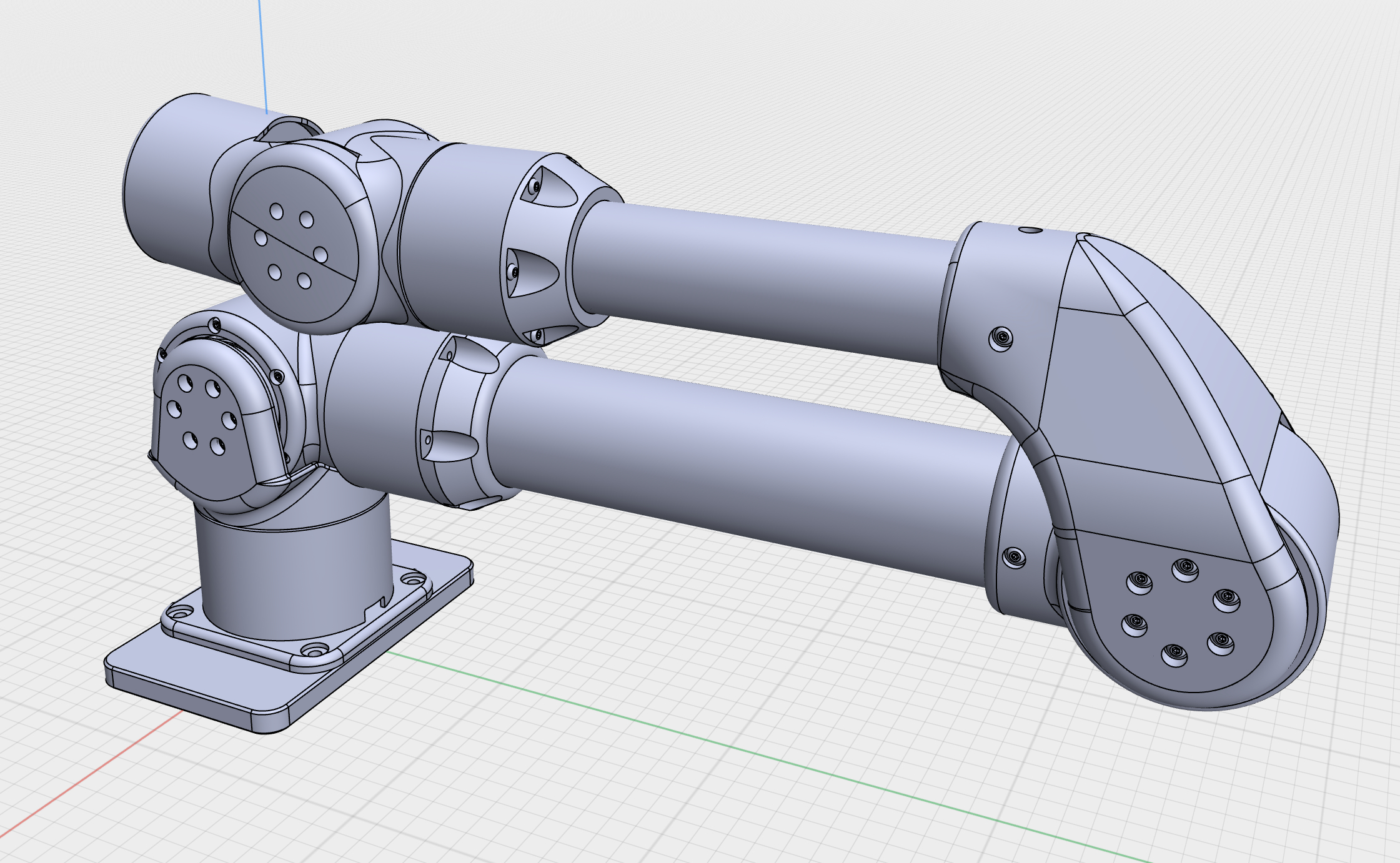
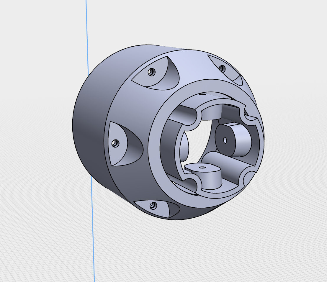
Iteration 2: Carbon Fiber Redesign (Design Study, Not Built)
- Redesigned around carbon fiber tube links with improved 3D-printed connection geometry between tubes and motors
- Intended material: PETG-CF
- Fully modeled in CAD; never physically manufactured or tested
- Informed the geometry decisions carried into Iteration 3
Iteration 3: CNC Sheet Metal Working Arm
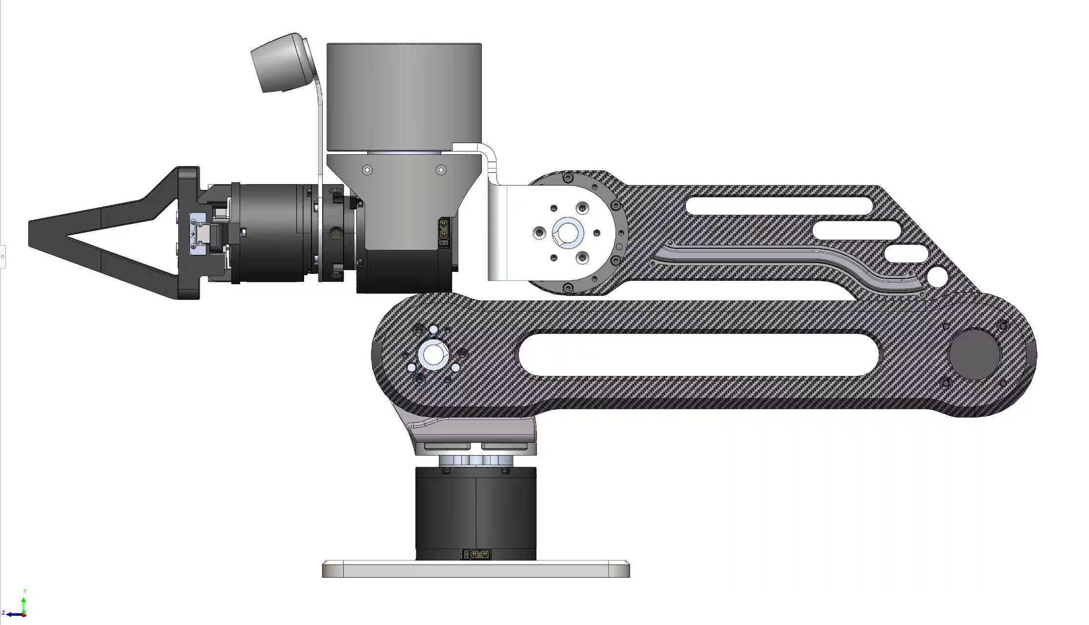
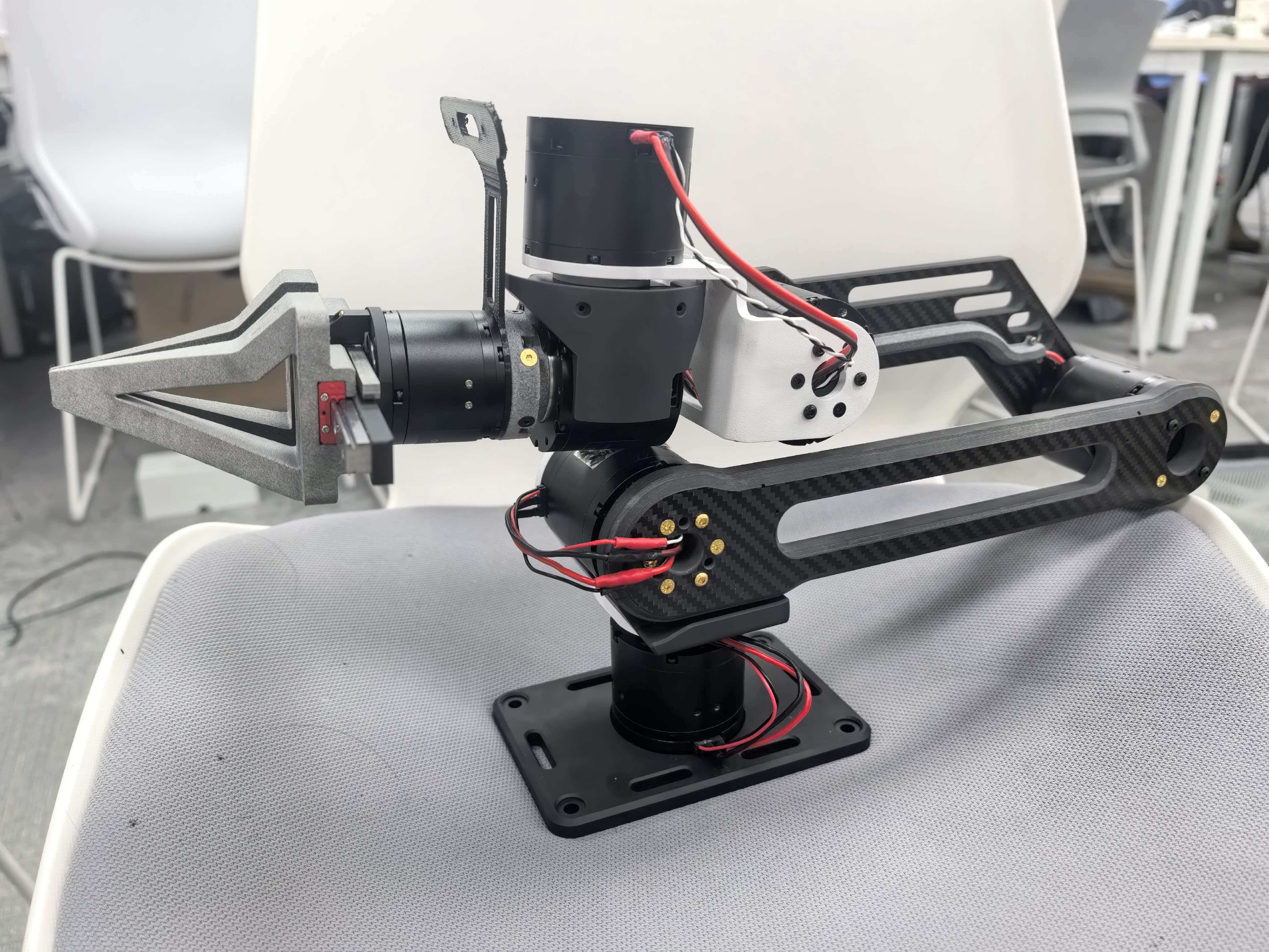
- Sheet metal, carbon fiber layup, and CNC-machined components, approximately 60cm workspace
- First fully working, precision-manufactured arm in the project, with meaningfully reduced structural flex compared to Iteration 1
- Used for robust demonstrations, including capability demos shown to potential industry partners
| Motor | Quantity | Rated Torque | Peak/Stall Torque |
|---|---|---|---|
| DM-3507 | 1 | 0.8 Nm | 3 Nm |
| DM-4310 | 1 | 3.5 Nm | 12.5 Nm |
| DM-4310P | 1 | 3.5 Nm | 12.5 Nm |
| DM-4340 | 1 | 9 Nm | 27 Nm |
| DM-4340P | 2 | 9 Nm | 27 Nm |
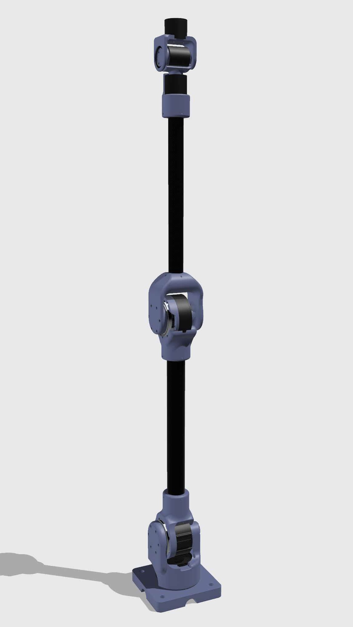
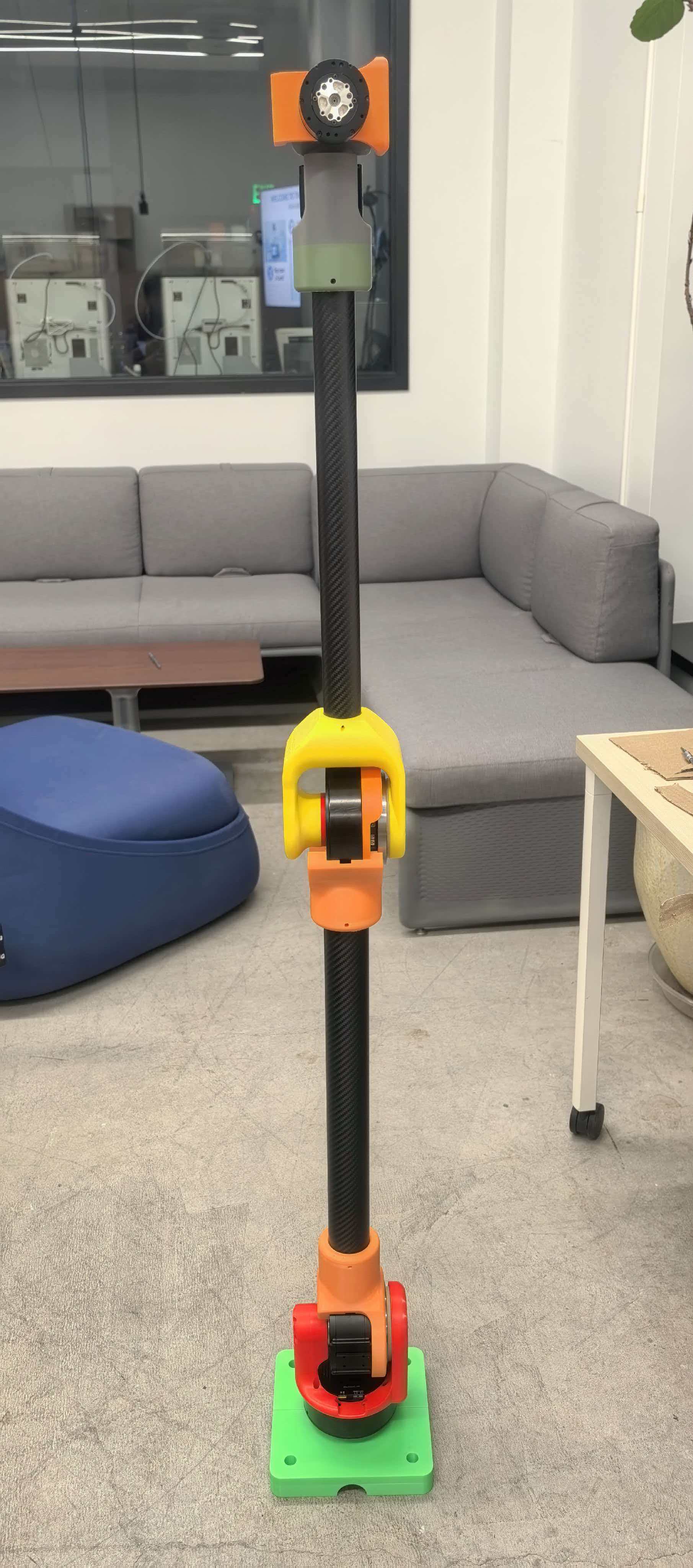
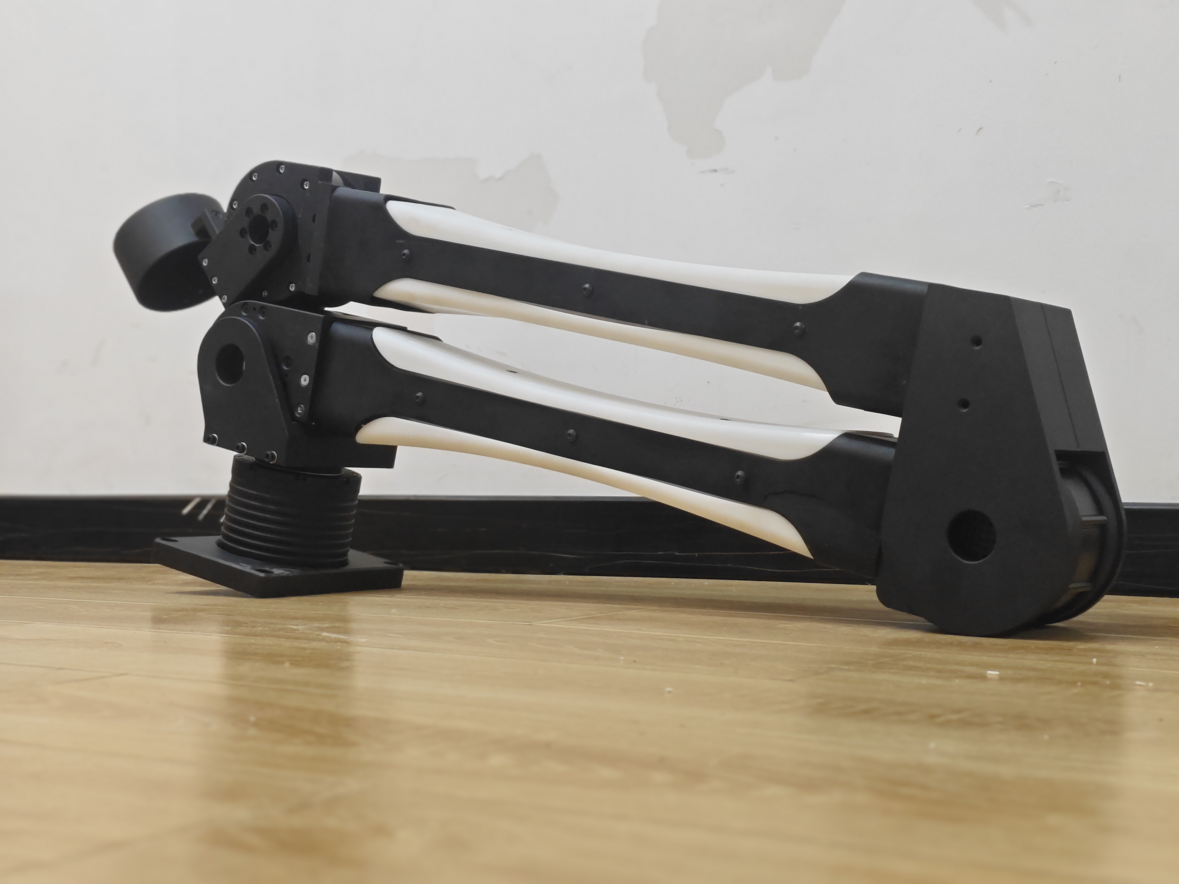
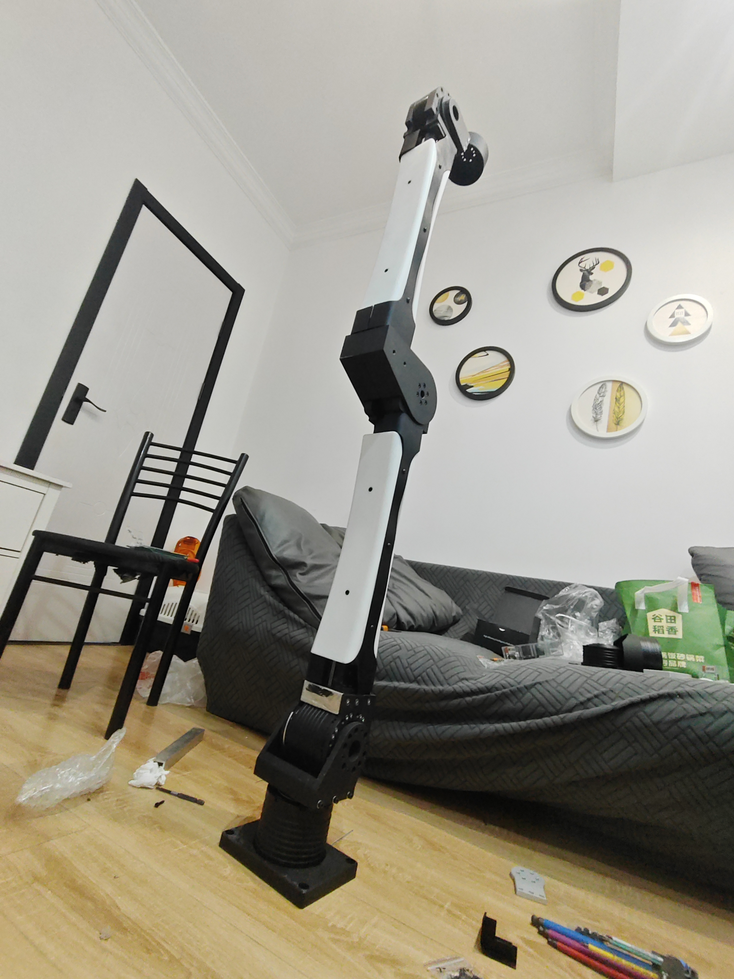
Iteration 4: 1.6m Scale Feasibility Prototype
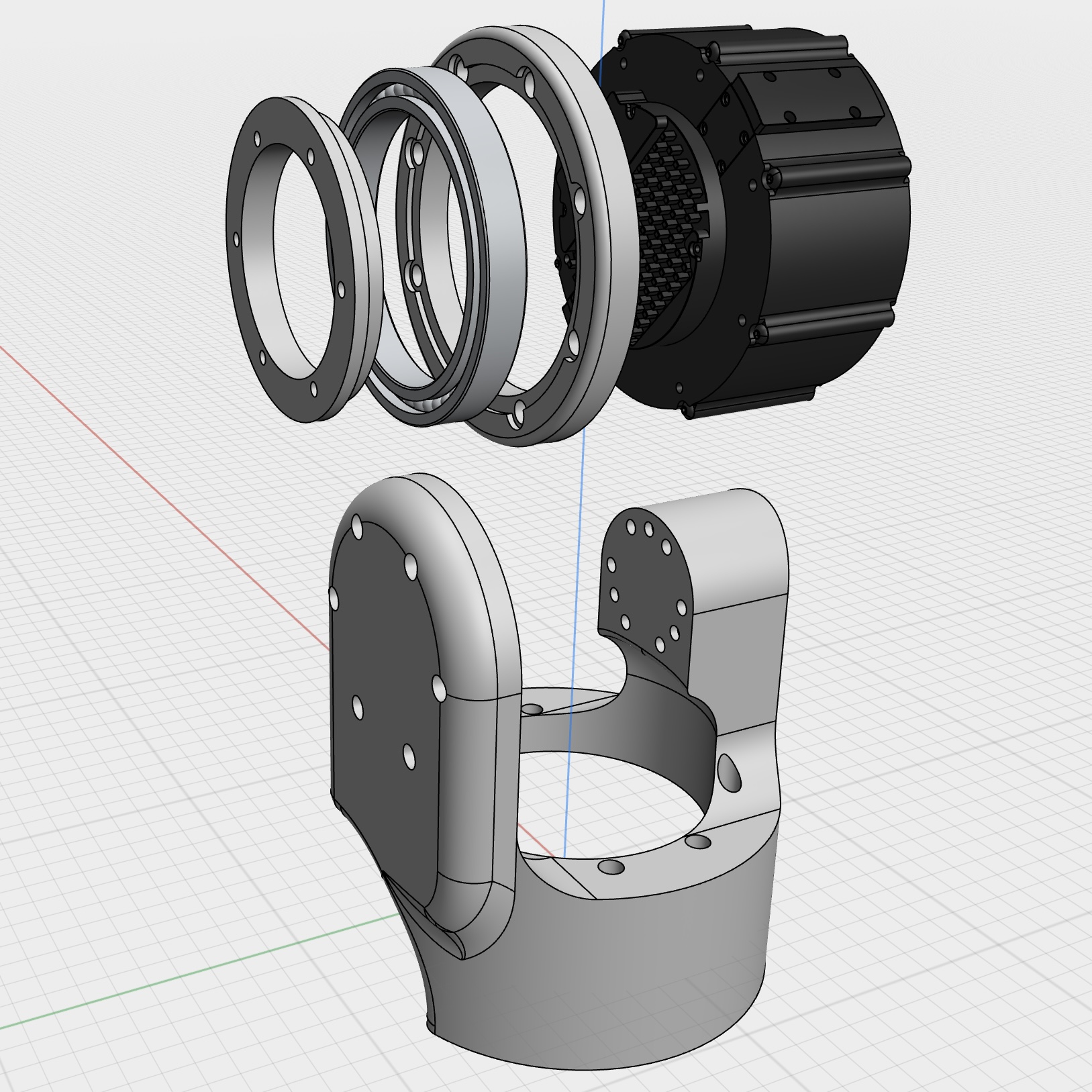
- 3D-printed joints paired with carbon fiber links at the full 1.6m target scale
- Built specifically to validate that the design could scale to a much larger workspace, a real requirement for cinematic motion control
- A structural feasibility proof, not a production design
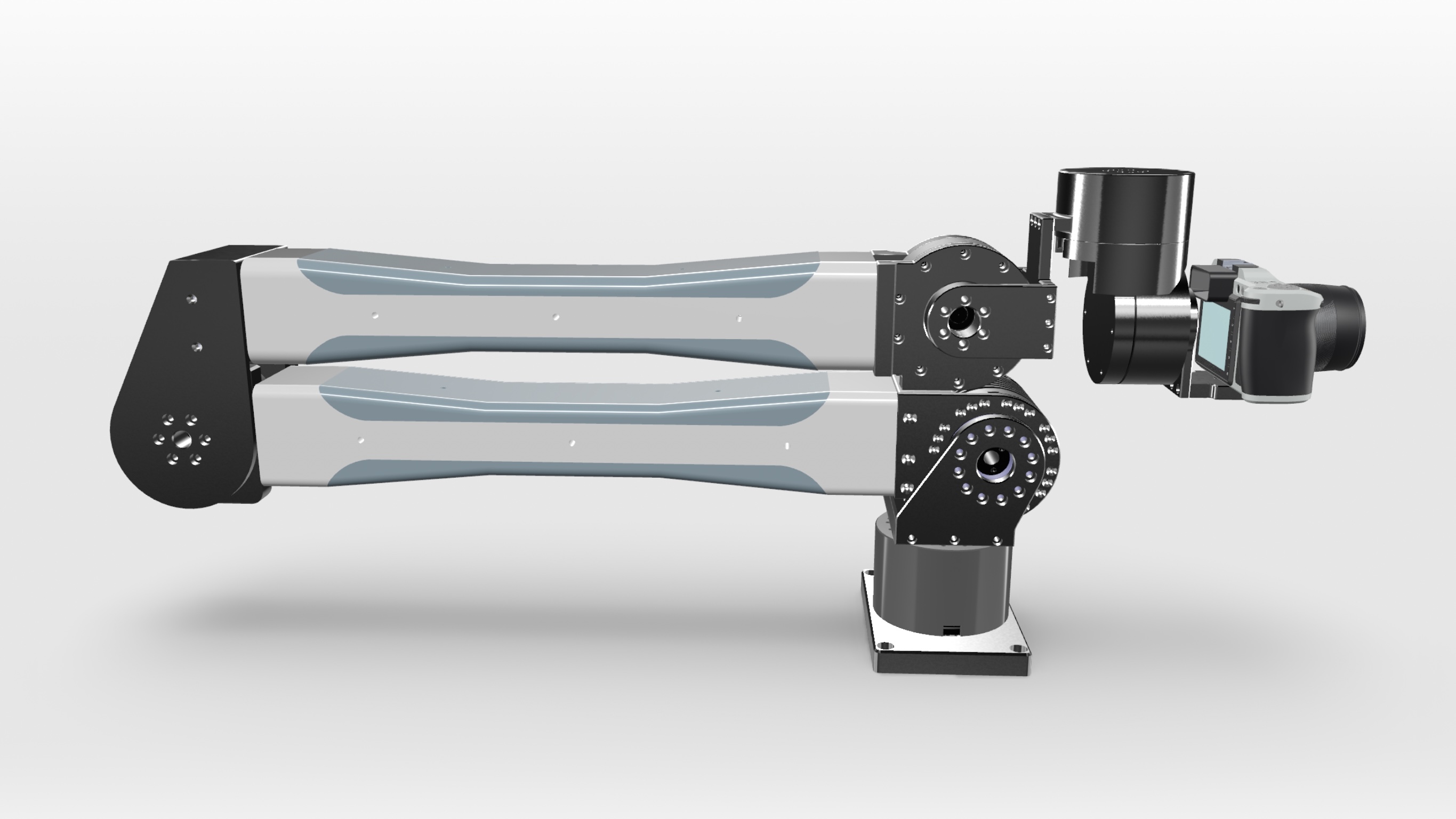
Iteration 5: Final CNC Aluminum Production Arm
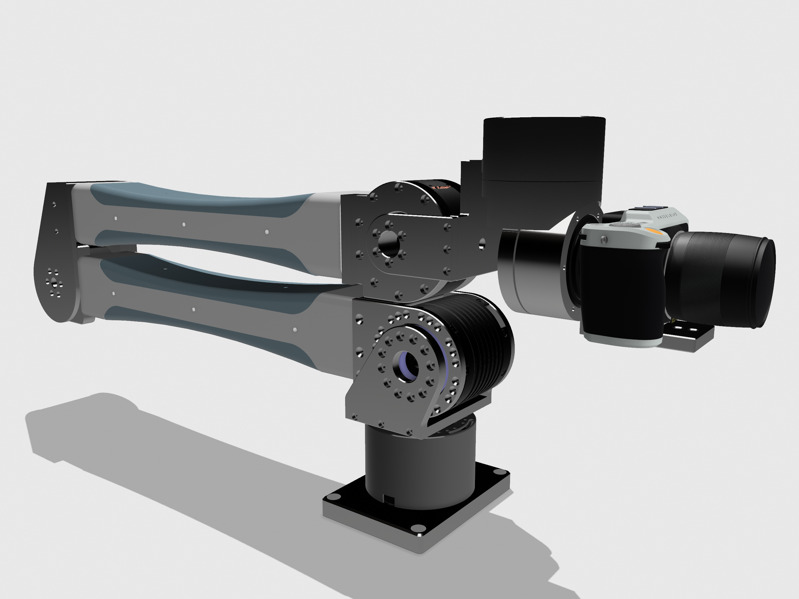
- Full CNC aluminum construction, 6 degrees of freedom, 1.6m span, 10kg payload capacity
- Cycloidal drive actuators, selected over harmonic drives for torque density and cost, with control algorithms adapted directly from published robotics research
- Each link decomposed into separate flat plates rather than a single complex piece, a design-for-manufacturability decision that significantly reduced CNC machining cost without compromising structural integrity
| Motor | Quantity | Rated Torque | Peak/Stall Torque |
|---|---|---|---|
| DM-10422 | 2 | 100 Nm | 400 Nm |
| DM-10010 | 1 | 40 Nm | 150 Nm |
| DM-10010L | 1 | 40 Nm | 120 Nm |
| DM-8009P | 2 | 20 Nm | 40 Nm |
Controls and Simulation
These control capabilities were developed and validated on Iterations 1 and 3; the final Iteration 5 arm inherits this proven control stack.
Control Architecture
- Began with PD control using the motor's built-in MIT mode, a common position and velocity control interface for high-performance quasi-direct-drive actuators
- Progressed to torque control using inverse dynamics, a whole-body, model-based approach that computes required joint torques directly from the arm's equations of motion
- This progression traded initial simplicity for the more sophisticated control needed for precise, compliant motion
Gravity Compensation
- Computes, in real time, the exact torque each joint needs to counteract gravity at its current configuration
- In practice, the arm holds any position it is released in without drifting, effectively feeling weightless to an operator
MuJoCo Sim-to-Real Pipeline
- Full physics model built by translating SolidWorks CAD directly into a MuJoCo XML model
- Exact rigid-body inertial properties (mass, center of mass, full 3x3 inertia tensor) extracted from SolidWorks for all 6 links, with rigorous unit conversion between CAD and simulation units
- Structured as a proper kinematic chain, with correct rotation axes matching the physical hardware's joint configuration
- Full rigid-body collision enabled on all links
- Validated through a live demonstration showing the simulated and physical arm moving in synchronized real time
Impedance Control
- Layers a virtual spring-damper relationship on top of gravity compensation, governing how the arm responds to external force rather than rigidly holding position
- Gives the arm a compliant, back-drivable feel; pushing on it moves it smoothly rather than fighting back
- Validated across multiple stiffness and damping settings
Kinesthetic Teaching
- An operator physically guides the end effector through a desired path while the system logs joint angles via high-frequency joint logging
- The recorded trajectory is replayed in position mode, reproducing the taught motion with sub-centimeter path repeatability
- Works reliably because gravity compensation removes the arm's own weight from the equation, and low-stiffness impedance control makes the arm easy to move by hand during teaching
Inverse Kinematics and Trajectory Planning
- Solves for joint angles that achieve a specified end-effector position and orientation
- Validated through a dedicated position control test sequence on the physical arm
- Applied practically to execute a vertical Resistive Force Theory probing motion, used to calibrate substrate coefficients for a separate locomotion research project (Terradynamics Lab)
Getting an accurate CAD-to-simulation pipeline working surfaced a series of concrete technical problems.
Solving Real Integration Problems
- A deprecated compiler attribute caused model load failures on newer versions of MuJoCo
- Initial inertia tensors failed a physical validity check, the triangle inequality between principal moments of inertia, resolved using MuJoCo's built-in inertia-balancing option
- Mesh alignment issues traced back to a mismatch between part-level and assembly-level coordinate frames during CAD export
- Resolved file compatibility issues between ASCII and binary mesh formats
Results
- Final arm: 6 degrees of freedom, 1.6m span, 10kg payload capacity, CNC aluminum construction, cycloidal drive actuation
- Five design iterations, four physically built
- Sub-centimeter path repeatability achieved through kinesthetic teaching and trajectory replay
- Sim-to-real pipeline validated through synchronized simulation and hardware demonstration
- Inverse kinematics control applied practically to support locomotion research in a separate lab
- Known limitation: high-speed trajectory tracking shows increased error due to imperfectly identified inertia parameters, an acceptable tradeoff given the arm's target application is inherently slow, smooth camera motion
Upcoming: A camera-specific redesign, targeting a tighter payload and reach envelope for cinematic use, is currently in the design and component-selection phase. Python-based control scripts for the MuJoCo model are also under active development as a pre-hardware testbed.