Toolhead-Following Model
Tracks which part of a tumor has already been resected as surgery happens, giving continuous visibility into surgical progress that single-frame segmentation alone cannot provide.
Four components, connected through a geometric construction rather than joint training:
- Tumor Boundary Segmentation, grounding the construction in the current tumor boundary
- Automatic Tool-Tip Seeding, locating the cutting instrument without a manual click
- Tool-Tip Tracking, following that point across the video
- Cutline-Sweep Mask Construction, combining trajectory and boundary into a running estimate of the resected region
Runs fully automatically, with no manual input required at any stage.
1. Tumor Boundary Segmentation
Same model as Stage 1 in the Margin Model.
2. Automatic Tool-Tip Seeding
- A Keypoint R-CNN detector proposes candidate tool-tip locations
- Detections are clustered by location to avoid duplicate detections on the same tool
- The detector locates the tool's inner tube rather than its distal cutting tip, leaving a systematic offset
- A two-pass SAM2 refinement corrects this using points sampled along the tool body
- A reliability check ensures refinement never performs worse than the raw detection
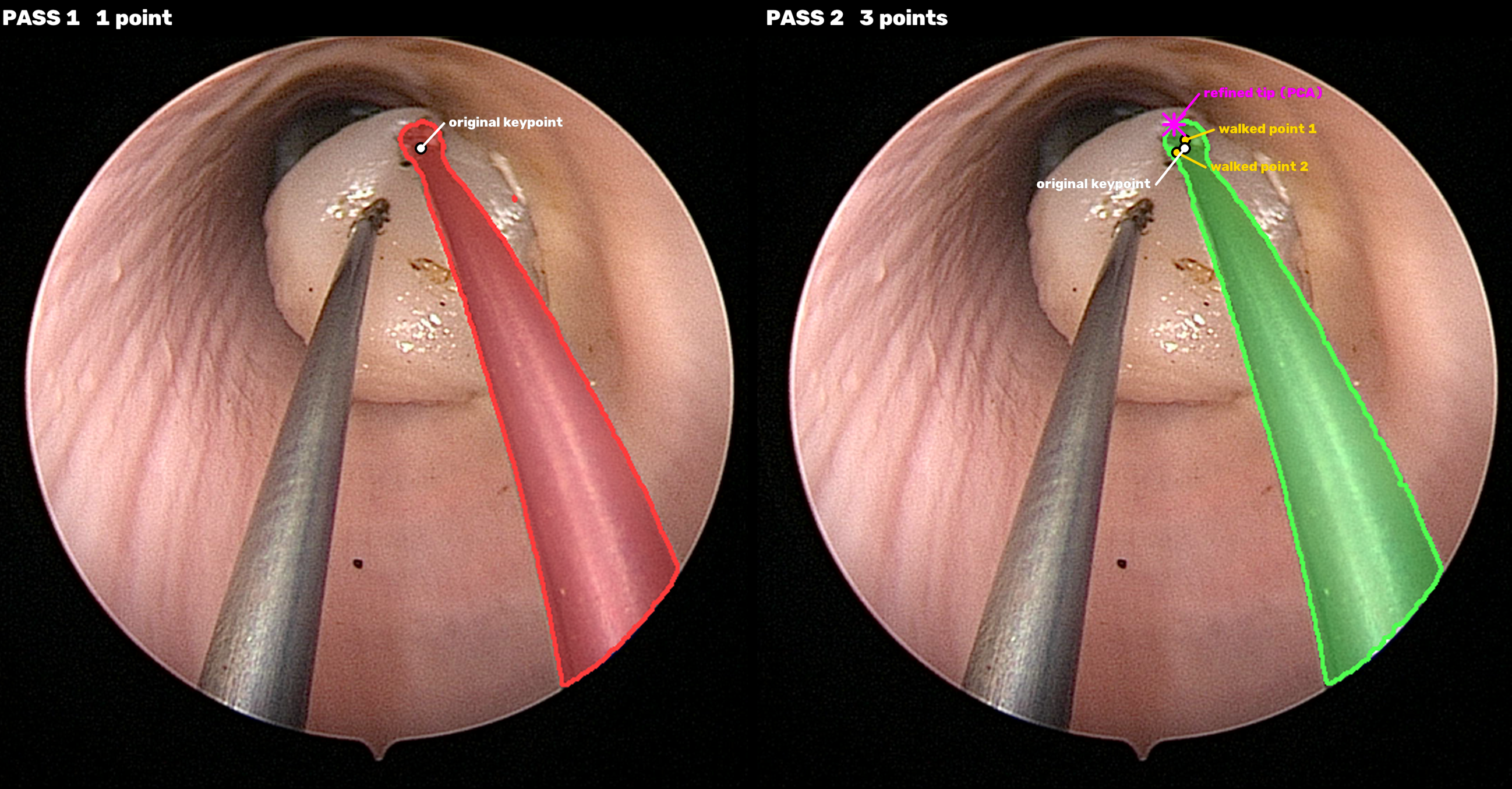
Before and After Refinement
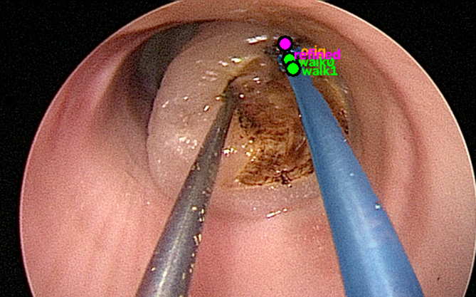
3. Tool-Tip Tracking
- Seeded tip position tracked across the video using a pretrained point tracker (TAPNext++), used without fine-tuning on surgical footage
- Reports a per-frame confidence flag
- A shaft-geometry fallback maintains a tip estimate during brief occlusions
- Tip positions smoothed with a moving average to reduce frame-to-frame noise
4. Cutline-Sweep Mask Construction
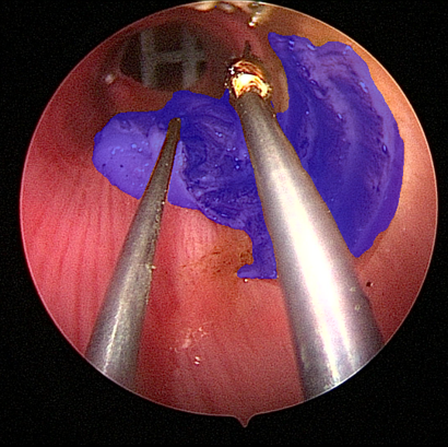
Combines the tracked tip trajectory with the live tumor boundary to build, frame by frame, an estimate of the resected region.
The Cutline
- Accumulated trajectory of the tracked tool tip
- Stored as a per-row array, updated as the tip moves
- Missing rows interpolated when the tip jumps across rows between frames
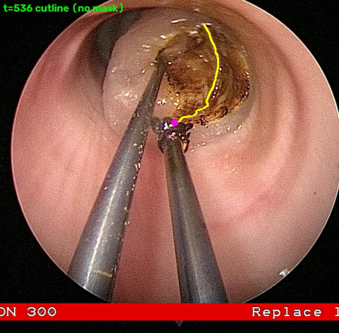
Mask Geometry, Three Edges
- Left edge: the cutline
- Right and top edges: the live tumor boundary from the Tumor Boundary Segmentation Model
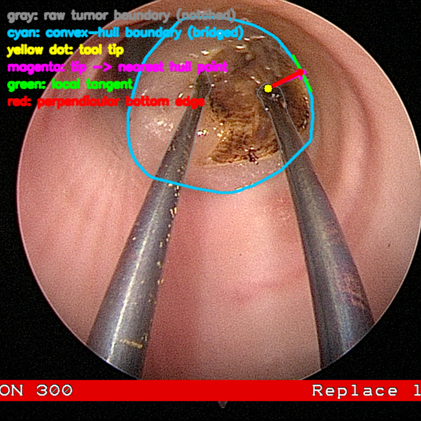
- Bottom edge: a segment anchored at the current tool tip, angled perpendicular to the local tumor-boundary tangent
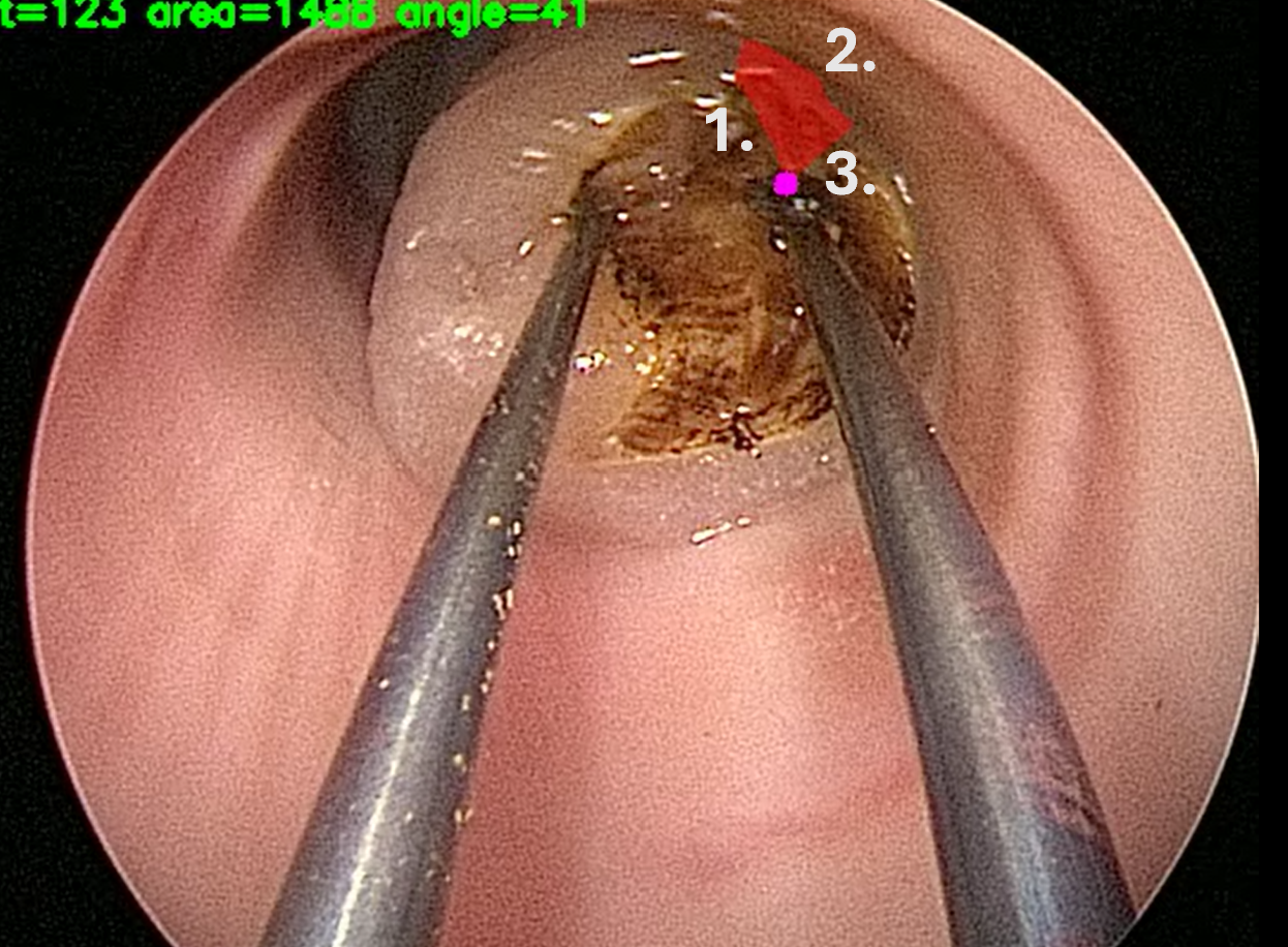
Computing the Perpendicular
- Convex hull of the tumor boundary taken first, bridging notches where the metal tool is excluded from segmentation
- Local tangent fit by principal component analysis over a small arc of hull points nearest the tool tip
- Tangent rotated 90 degrees to obtain the perpendicular bottom edge
Where the Cut Begins
- Starting condition determined once per video
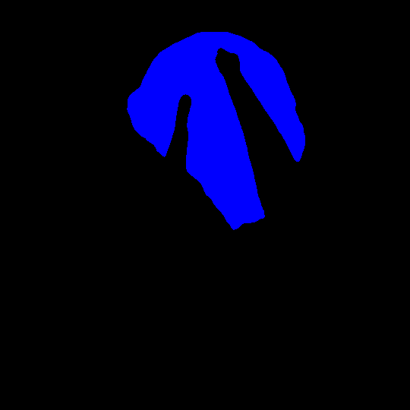
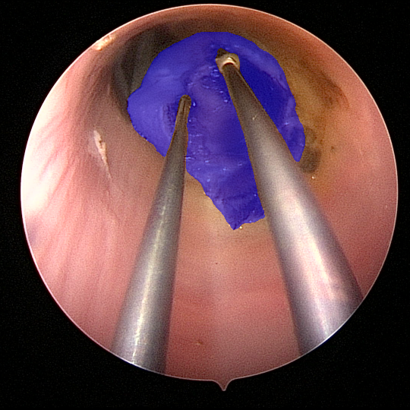
- Case A: tumor mask is a single connected region, tip started inside the tumor. Top edge anchored to the cutline entry point
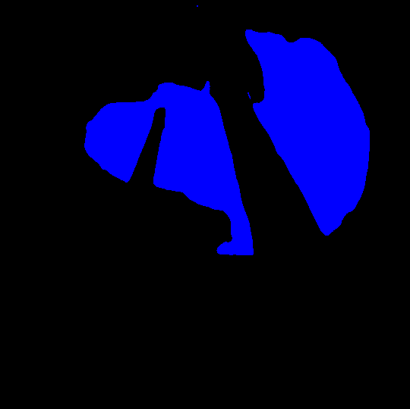
- Case B: tumor mask is split into two regions, tool shaft entered from outside. Top edge remains the tumor boundary until the tip enters and the mask reconnects
5. Accumulation Across Frames
accum_mask = (accum_mask OR frame_mask) AND T- accum_mask: running total of every pixel ever marked resected
- frame_mask: current frame's candidate resected region
- T: current frame's tumor boundary mask
- OR adds this frame's newly resected region; pixels already marked stay marked
- AND drops any accumulated pixel the current segmentation no longer classifies as tumor, allowing the mask to self-correct
Results
- Formal evaluation against ground-truth resection annotations has not yet been completed, since no such annotation currently exists for this task
- The tracker's self-reported tracking confidence averaged 97.3 percent across a set of test videos
- Robustness is primarily demonstrated through the videos throughout this page